1. Why PET Bottle Manufacturers Are Moving to One-Step ISBM
Australia’s packaged beverage market — worth over AUD 14 billion annually and growing at roughly 3% per year — depends on PET bottles that are simultaneously lighter, stronger, more transparent, and more economical to produce than any previous packaging format. The technology that makes this combination possible at commercial scale is the one-step injection stretch blow moulding machine, a platform that has progressively displaced two-step reheat blow moulding as the preferred choice for mid-volume beverage, food, pharmaceutical, and personal care manufacturers across Australia and globally.
The numbers explain the shift clearly. A one-step automatic ISBM machine consumes 20–30% less energy than an equivalent two-step line by eliminating the reheat penalty entirely. Material utilisation exceeds 95%, compared with 85–92% for extrusion blow moulding. The biaxial molecular orientation achieved in the stretch-blow station increases container tensile strength by more than 30% over unoriented PET. A single operator can run a four-station machine through a full shift. Mould changeovers take under 60 minutes. And the closed-loop process — from raw resin pellet to finished food-safe container with no intermediate atmospheric exposure — gives one-step technology a hygiene architecture that two-step processing cannot structurally replicate.
Understanding why these performance numbers are achievable requires a detailed look at what actually happens inside a one-step ISBM machine at each production station. That is precisely what this guide provides — a complete engineering walkthrough of the PET bottle production process, from resin specification through to container ejection, written for engineers, production managers, and capital equipment decision-makers who need more than marketing headlines to justify a platform investment.
2. PET Resin: The Starting Material and Why Specification Matters
Every PET beverage bottle begins as a small, semi-transparent granule of polyethylene terephthalate (PET) resin approximately 3–4 mm in diameter. The intrinsic viscosity (IV) of this resin — a measure of molecular chain length — is the single most important raw material parameter in ISBM processing. Beverage-grade PET for carbonated soft drink (CSD) bottles typically specifies an IV of 0.78–0.84 dL/g; still water and juice applications can use slightly lower IV in the 0.72–0.78 range; hot-fill containers require higher IV (0.80–0.86) to resist thermal deformation during the filling process. Using the wrong IV grade introduces processing problems — low IV resin produces hazy bottles with inadequate burst pressure; high IV resin requires higher injection pressure and generates more shear heating, which can cause yellowing and acetaldehyde formation that affects beverage taste.
2.1 Drying: The Critical Pre-Process Step
PET is hygroscopic — it absorbs atmospheric moisture readily, and even trace moisture (above 50 ppm) causes hydrolytic degradation during the high-temperature injection process, breaking molecular chains and irreversibly reducing IV. Before processing on a PET bottle blowing machine, PET resin must be dried in a desiccant dehumidifying dryer to a moisture content below 50 ppm — and ideally below 30 ppm for beverage-grade containers. Drying conditions: 160–170 °C for 4–6 hours, with desiccant bed dewpoint held at −40 °C or below. Inadequate drying is the most common cause of haze, brittleness, and reduced impact resistance in ISBM-produced containers, and it is a process step that occurs entirely upstream of the machine itself — making dryer specification as important as machine specification for consistent container quality.
2.2 rPET Integration in the Australian Context
Australia’s packaging sustainability framework, coordinated through APCO (Australian Packaging Covenant Organisation), is progressively increasing mandatory recycled content requirements for PET beverage packaging. One-step ISBM machines are inherently better suited to processing rPET blends than two-step reheat lines because there is no separate reheat infrared oven to recalibrate for the different near-infrared (NIR) absorption characteristics of rPET versus virgin PET. The injection barrel of a one-step machine processes rPET through a temperature-controlled melt path regardless of its NIR properties, enabling stable processing of blends from 25% to 100% rPET with appropriate IV and colour specification. Australia Ever-Power’s servo-controlled injection units maintain melt temperature consistency within ±2 °C across the full barrel length, which is the foundation for repeatable container quality when running variable rPET feedstocks.
| Application | IV (dL/g) | Drying Temp | Drying Time | Max Moisture |
|---|---|---|---|---|
| Still water / juice | 0.72–0.78 | 160–165 °C | 4 h | 50 ppm |
| CSD / sparkling water | 0.78–0.84 | 165–170 °C | 5–6 h | 30 ppm |
| Hot-fill (juices, teas) | 0.80–0.86 | 170 °C | 6 h | 30 ppm |
* IV = Intrinsic Viscosity. Values are guidelines; confirm with resin supplier data sheet for specific grades.
3. The Four-Station Process: What Happens at Each Stage
A four-station one-step injection stretch blow moulding machine operates as a rotary platform where all four stations act simultaneously during each machine cycle. As the index table rotates 90°, a new preform is injected at Station 1 while the preform from the previous cycle is being conditioned at Station 2, stretched and blown at Station 3, and the finished container is being cooled and ejected at Station 4. This parallel operation is why cycle times of 10–30 seconds are achievable — the machine does not wait for one station to complete before starting the next.
3.1 Station 1 — Injection Moulding: Forming the Preform
Dried PET granules are fed from the hopper into a reciprocating screw plasticising unit, where they are heated to 270–290 °C across multiple independently controlled barrel zones. The screw rotation simultaneously melts the resin and builds shot pressure, then drives the melt at controlled velocity through the hot-runner manifold and into the closed preform mould cavity. The core rod — a precision-ground steel pin that forms the internal bore of the preform — defines the inner wall surface, while the cavity mould defines the outer wall and forms the complete threaded neck finish. Injection pressure typically ranges from 80–140 MPa, held for a programmed pack-and-hold phase of 2–5 seconds to compensate for volumetric shrinkage as the melt cools. The result is a precisely dimensioned preform with wall thickness uniformity critical to achieving consistent orientation in the subsequent stretch-blow station. The threaded neck is formed to its final dimension here and never exposed to heat or pressure again — guaranteeing the dimensional stability of the closure interface throughout the container’s production and service life.
3.2 Station 2 — Temperature Conditioning: The Thermal Foundation of Quality
This station is the engineering innovation that defines the one-step injection stretch blow moulding machine and separates it from all two-step architectures. Rather than cooling the preform to ambient temperature and reheating it — the thermally wasteful route that two-step lines must take — the one-step machine retains the preform on its core rod and uses zoned temperature management to bring it to the precise thermal condition required for optimal biaxial stretching. The body temperature is held or adjusted to 95–110 °C (the ideal stretch window for standard beverage-grade PET) while the neck region is actively cooled below 70 °C using an internal cooling circuit through the core rod. This differential thermal profile — body hot, neck cold — is what allows simultaneous stretch of the preform body and dimensional stability of the neck thread during the blowing cycle. The conditioning station uses precision-controlled heater banks or infra-red elements with independent zone control, enabling the temperature profile to be tuned for different wall thicknesses, resin grades, and container designs without changing hardware.
3.3 Station 3 — Stretch and Blow: Where Molecular Architecture Is Built
The stretch-blow station is where the mechanical properties of the finished container are fundamentally determined. The conditioned preform is transferred into the blow mould cavity, the mould closes and clamps at the designed clamping force, and the stretch rod descends axially through the core rod — elongating the preform body in the axial direction at a controlled velocity (typically 1.0–1.5 m/s). Simultaneously, pre-blow air at 0.5–0.8 MPa begins to expand the preform radially, preventing the sidewall from folding as the rod stretches it. Once the rod reaches full extension, the main blow air — at 2.5–4.0 MPa, controlled to ±0.05 MPa — is admitted to force the preform wall outward against the blow mould surface. The dual mechanical and pneumatic stretching creates biaxial molecular orientation: PET chains are simultaneously aligned in the axial (vertical) and hoop (circumferential) directions, which increases tensile strength by more than 30%, dramatically improves optical clarity, and substantially reduces gas permeability. The total stretch ratio (axial × radial, typically 2.5 × 3.5) must be matched to the preform design and resin IV — under-stretching leaves excessive material in the base and sidewall without full orientation; over-stretching causes whitening (stress-whitening) and potential stress cracking under pressure.
3.4 Station 4 — Cooling and Ejection: Dimensional Setting and Output
After blow moulding, the finished container must be held against the cooled blow mould surface long enough for the PET to solidify and for the crystalline orientation to be locked in. Cooling water at 8–15 °C circulates through the blow mould channels, and the container dwells under internal air pressure for 5–20 seconds (depending on wall thickness and container volume) before the mould opens. Premature mould opening — before the container wall has fully set — causes shrinkage, dimensional non-conformance, and base panelling under subsequent filling pressure. The cooling time is therefore a production rate constraint: reducing it below the minimum required for full dimensional setting saves cycle time but increases defect rate in downstream filling and labelling operations. After ejection, the container is conveyed directly to the downstream packaging line — the entire process from resin to finished container is complete, with no further temperature steps, no inspection holding area, and no second machine required.
4. Critical Process Parameters and Their Effect on Container Quality
Each parameter in the ISBM cycle is interdependent — a change at Station 1 propagates effects through Stations 2, 3, and 4. The table below maps the most critical parameters to their quality outputs and the consequences of deviation.
| Параметр | Typical Range | Effect on Container Quality | Deviation Risk |
|---|---|---|---|
| Melt temperature | 270–290 °C | Clarity, IV retention, acetaldehyde level | High → yellowing, AA; Low → incomplete fill, haze |
| Preform body temp (conditioning) | 95–110 °C | Stretch ratio uniformity, wall thickness distribution | High → thin base, blowouts; Low → stress-white, uneven wall |
| Stretch rod speed | 1.0–1.5 m/s | Axial orientation level, material distribution | Too fast → base thinning; Too slow → inadequate axial orientation |
| Blow pressure (main) | 2.5–4.0 MPa | Hoop orientation, container volume accuracy | Low → incomplete expansion, oval cross-section |
| Cooling dwell time | 5–20 s | Dimensional stability, base integrity | Short → base panelling, ovality, shrinkage defects |
| Injection pack pressure | 80–140 MPa | Preform wall uniformity, sink marks, flash | High → flash, stress cracking; Low → sinks, short shots |
* Ranges are indicative for standard beverage-grade PET. Adjust for specific resin grades, wall thicknesses, and container geometries.
5. Mould Tooling: The Interface Between Machine and Container
The mould tooling on a one-step automatic ISBM machine consists of three interdependent components: the injection preform mould, the blow mould, and the core rods. Each must be designed as a system — the preform geometry drives the stretch ratio at each point on the container wall, which in turn drives the orientation level and material distribution in the finished bottle. Poor preform design is the leading cause of unexplained container failure in ISBM production, and it cannot be fully corrected by adjusting machine parameters alone.
5.1 Preform Design Principles
The preform wall thickness profile controls the material distribution in the blown container. The base of the preform must carry more material than the sidewall — the base gate area stretches less than the sidewall during blowing and therefore requires additional material to achieve equivalent wall thickness in the finished container. The gate geometry (the injection point at the base of the preform) must be designed to minimise gate vestige height, as any protrusion becomes a potential stress concentrator under base-drop impact testing — a critical requirement for carbonated beverage bottles under AS/NZS packaging standards applicable in Australia. The gate vestige should ideally be recessed below the outer radius of the container base.
5.2 ASB Mould Compatibility: A Practical Advantage
Australia Ever-Power’s full range of injection stretch blow moulding machines is engineered for direct dimensional compatibility with Japanese ASB (Aoki Sidel Blow) machine mould tooling. For manufacturers who have invested in ASB preform and blow mould sets — often representing an investment of AUD 50,000–200,000 per format depending on cavity count and complexity — this compatibility means that migrating to Australia Ever-Power equipment does not require new tooling fabrication. The core rod diameter, neck ring geometry, and blow mould split-line references all match the ASB standard. This single design decision removes the most common financial barrier to platform migration and is particularly valuable in the Australian market where the installed base of ASB equipment is substantial.
5.3 Mould Materials and Maintenance
Injection preform moulds are typically fabricated from hardened tool steel (P20 or H13) for long-run stability — cavity surface hardness of 50–54 HRC is standard for commercial beverage production volumes. Blow moulds can use beryllium-copper alloy inserts at the base and base push-up area where cooling efficiency and heat extraction rate most directly affect cycle time, with aluminium alloy for the body sections where surface detail reproduction and weight reduction are priorities. Preventive maintenance on the core rod sealing faces — which must maintain a gas-tight interface during the blow cycle — should be scheduled every 500,000 cycles, with visual inspection of the core rod surface finish at each mould change to detect the early stages of erosion that precede seal failure and air leakage.
6. Container Quality Verification: What to Measure and Why
Producing a container that looks acceptable is not the same as producing a container that will survive filling, capping, labelling, distribution, and end-use under the conditions for which it was designed. A structured quality verification programme for ISBM-produced PET beverage bottles covers four categories of measurement, each targeting a different failure mode.
📐 Dimensional Inspection
- Neck finish OD and thread profile (± 0.1 mm)
- Body diameter and height (± 0.3 mm)
- Base push-up height (critical for stability)
- Wall thickness at 6 measurement points via ultrasonic gauge
💪 Mechanical Performance
- Top-load compression (minimum 150 N for 500 mL CSD)
- Burst pressure test (minimum 1.5× filling pressure)
- Drop impact test (1.5 m drop, filled and capped)
- Creep resistance at 40 °C (distribution simulation)
🔬 Optical Quality
- Haze measurement (target < 2% for clear PET)
- Visual inspection for gate marks, flow lines, and sink marks
- Colour delta-E versus approved reference standard
🧪 Barrier & Food Safety
- Acetaldehyde content (target < 10 μg/L for water bottles)
- CO₂ permeability for CSD applications
- Oxygen transmission rate for juice / dairy
- FSANZ food-contact migration test (for new tooling)
Australia Ever-Power provides a factory acceptance test (FAT) report with every machine shipment, including measured container samples from the specific tooling set covering all four quality categories above. For pharmaceutical and food-grade installations, third-party witnessed FAT with full traceability documentation is available on request, supporting TGA facility registration and FSANZ food safety management system audit requirements.
7. Selecting the Right PET Bottle Blowing Machine for Your Production Requirements
Australia Ever-Power’s ISBM product range spans three-station to four-station configurations, clamping forces of 50–250 tonnes, and standard servo to fully servo drive systems. Matching machine specification to production requirements across five dimensions ensures that neither output capability nor energy efficiency is compromised by an incorrect selection.
7.1 Annual Volume and Cavity Configuration
The three-station HGY50-V3-EV is sized for annual outputs up to approximately 5 million units in standard 500 mL format, making it the right starting point for new market entrants or speciality premium beverage brands with volume requirements that do not justify a four-station investment. The four-station HGYS150-V4 and HGYS200-V4 models address the 5–20 million unit annual band that covers the majority of Australian mid-market beverage manufacturers. For outputs beyond 20 million units, multi-cavity tooling configurations should be evaluated — the marginal cost of adding a second cavity within an existing four-station machine clamping envelope is substantially lower than purchasing a second complete machine, and the operational benefit of a single machine platform (one operator, one maintenance schedule, one control system) compounds over the machine’s service life.
7.2 Container Volume Range and Base Design
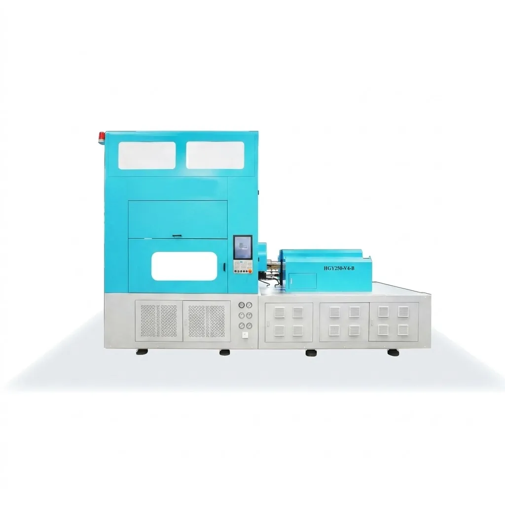
The HGYS200-V4-B and HGY250-V4 models are rated for containers up to 20 L and are the correct choice for large-format water dispensing bottles, edible oil, or industrial liquid containers. The critical selection parameter for large-volume containers is not just the blow mould cavity volume but the clamping force — as container diameter increases, the projected area of the blow mould exposed to internal blow pressure requires proportionally higher clamping force to prevent mould flash at the parting line. Under-specifying clamping force for a large-diameter container is a common selection error that results in persistent flash that cannot be eliminated through process adjustment alone.
7.3 Full Servo vs Standard Servo Drive Systems
Full servo drive (EV series models) replaces all hydraulic actuation with electric servo motors, delivering 15–25% additional energy reduction over standard servo-hydraulic hybrid configurations — stacked on top of the 20–30% one-step ISBM advantage over two-step processing. The full servo automatic ISBM machine also offers faster and more repeatable motion control, reduced hydraulic fluid inventory and disposal costs, lower noise levels (relevant for urban industrial estates in Sydney and Melbourne), and improved suitability for cleanroom-adjacent pharmaceutical packaging environments. For operations with specific ESG reporting commitments or Australian Carbon Credit Unit (ACCU) generation targets, the quantifiable Scope 2 emissions reduction from upgrading to full servo drive is directly reportable under the ASRS framework applicable to ASX-listed entities.
8. Common Defects, Root Causes, and Corrective Actions
Production defects in ISBM operations follow predictable patterns. The following troubleshooting matrix addresses the six most commonly reported container defects, their primary root causes, and the corrective process adjustment or tooling action required to resolve them.
9. Australia Ever-Power ISBM Equipment Range Overview
Australia Ever-Power (27 Harley Crescent, Condell Park NSW 2200) is the Australia-based manufacturer and supplier of the HGYS and HGY series one-step injection stretch blow moulding machines, with 18 years of specialist engineering experience and 56 completed installations globally. The table below summarises the current product range by key specification.
| Model | Stations | Drive | Max Volume | Найкраще застосування |
|---|---|---|---|---|
| HGY50-V3-EV | 3 | Full Servo | ~2 L | Speciality beverages, cosmetics, pharma vials |
| HGYS150-V4 | 4 | Servo | ~5 L | Mid-volume water, juice, CSD bottles |
| HGYS150-V4-EV | 4 | Full Servo | ~5 L | ESG-focused lines, pharma, premium beverage |
| HGYS200-V4 / V4-B | 4 | Servo | ~10 L | Edible oil, dairy, large-format water |
| HGY250-V4 / V4-B | 4 | Servo | 20 L | Water dispensing, industrial containers, handled bottles |
All models support ASB mould compatibility, ≤60-minute mould changeover, remote PLC diagnostics, and ISO 9001:2015 quality documentation. Custom configurations — non-standard neck finishes, multi-layer barrier containers, or modified station geometries — are available with a minimum lead time of 35–50 business days from approved drawing.


